SHBootMode
From OpenECU
(→Build the hardware) |
|||
| Line 6: | Line 6: | ||
===Build the hardware=== | ===Build the hardware=== | ||
| - | You need to build a serial interface with which to talk to the CPU. The schematic for this interface is shown below. EcuFlash only supports FTDI based USB to serial interfaces. The schematic below shows what the interface must look like. You could build this by taking apart a FTDI-based USB to serial device and making the needed modifications. Basically, this is a simple TTL-level serial interface where the raw TXD and RXD signals are taken from the FTDI chip. There is also a 555 timer based circuit to provide the watchdog signal while in the boot mode. | + | You need to build a serial interface with which to talk to the CPU. The schematic for this interface is shown below. EcuFlash only supports FTDI based USB to serial interfaces. The schematic below shows what the interface must look like. You could build this by taking apart a FTDI-based USB to serial device and making the needed modifications, or there are many FTDI based evaluation and prototyping modules which can be used. Basically, this is a simple TTL-level serial interface where the raw TXD and RXD signals are taken from the FTDI chip. There is also a 555 timer based circuit to provide the watchdog signal while in the boot mode to prevent the CPU from resetting. |
'''[http://openecu.org/downloads/shbootmode.pdf Download SH Boot Mode Schematic Here]''' | '''[http://openecu.org/downloads/shbootmode.pdf Download SH Boot Mode Schematic Here]''' | ||
Revision as of 00:43, 16 January 2009
Contents |
Reflashing Subaru SH705x ECUs using the Renesas boot mode
Summary
If a Subaru ECU becomes unresponsive due to an incorrect or incomplete reflash, it is possible erase and reflash the SH705x CPU using the built in boot mode by utilizing some special hardware and EcuFlash. This page describes the procedure step-by-step.
Build the hardware
You need to build a serial interface with which to talk to the CPU. The schematic for this interface is shown below. EcuFlash only supports FTDI based USB to serial interfaces. The schematic below shows what the interface must look like. You could build this by taking apart a FTDI-based USB to serial device and making the needed modifications, or there are many FTDI based evaluation and prototyping modules which can be used. Basically, this is a simple TTL-level serial interface where the raw TXD and RXD signals are taken from the FTDI chip. There is also a 555 timer based circuit to provide the watchdog signal while in the boot mode to prevent the CPU from resetting.
Download SH Boot Mode Schematic Here
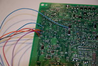
Connect the hardware to the ECU
Make the connections diagrammed in the schematic. If the test points listed in the schematic (Pxxx) are not on your ECU PCB, you should be able to find the needed pads by tracing them from the CPU pins (also listed in the schematic).
Power the ECU
You will also need to provide the ECU with +12V and ground on the power supply pins.
Obtain the ROM
Since the boot mode is a write-only operation, you will need the complete ROM you intend to reflash the ECU with. Make note of the XML ID of this ROM as you will need to modify its XML metadata in the next step.
Turn on SH Boot Mode in EcuFlash
Go to File -> Options -> Force SH Boot Mode and check the box. Remember to uncheck this after you are done.
This will tell EcuFlash to use the SH boot mode method instead of the standard kernel based reflash method.
Start EcuFlash
You must start / restart EcuFlash to read the XML changes
Load the ROM
Flash the ROM to the ECU
This is a slow process as compared to a standard reflash!


